ยี่ห้อ
 หมวดสินค้า
 ข้อมูล

 (Litech)-120x120.jpg)

 Full-120x120.jpg)
/01 Control Cable/02 With Shield Foil/Multi Cores/Multiconductors Foiled Shielded Single-120x120.jpg)


-120x120.jpg)

-120x120.jpg)
-120x120.jpg)
-120x120.jpg)


-120x120.jpg)
-120x120.jpg)

 ตะกร้าสินค้า
 สินค้าของเรา
-120x120.jpg "Coaxial Cable RG 179")

DIN Female To N Male Adaptor/L29(7;16)DIN Female To N Male Adaptor-120x120.jpg "L29(7/16)DIN Female To N Male Adaptor")


/09 C4 50ohm Male Straight PCB Mount Type/C4 50ohm Male Straight PCB Mount Type-120x120.jpg "C4 50ohm Male Straight PCB Mount Type")

-120x120.jpg "BNC Female-Female Adapter (Non Panel Mount)")
-120x120.jpg "19\" HIGH QUALITY EXPORT RACK 42U (60x80 cm.)")
/02 Network Cable/03 Computer Cable/02 High Speed Data Cables/Multipairs Foiled Shield (CM)-120x120.jpg "Multipairs Foiled Shield (CM) 24 AWG (7/0.2) 12 Pairs")
-120x120.jpg "21\" TELECOM OPEN RACK (2200Hx600Wx300D mm.)")

/05 Special Cable/06 UL 1015 CSA TEW/UL 1015 CSA TEW-120x120.jpg "Appliance Wiring Material UL 1015 CSA TEW Solid 0.13 sq.mm. (26 AWG)")


/01 Control Cable/03 With Shield Foil + Braid/Multi Pairs/Multipairs Foiled Copper Braided Shielded 01-120x120.jpg "สายเคเบิ้ล คอนโทรล มัลติแพร์ แบบมีชิลด์ฟลอยด์ และ ชิลด์ถักทองแดง 1.25 ตร.มม. (16 AWG) 6 คู่")
/08 VINYL-INSULATED BLADE TERMINALS-120x120.jpg "หัวเสียบก้านไม้ขีดแบบแบน หุ้มไวนีล (0.5 - 1.5 ตร.มม.) DBV1-18")

/02 RF Cable (Corrugated Copper tube) HCTAY(Z)-50-22(78”)50-22(78”)/RF Cable (Corrugated Copper tube) HCTAY(Z)-50-22(78”)50-22(78”) 00-120x120.jpg "RF Cable (Corrugated Copper tube) HCTAY(Z)-50-22(7/8”)")

/01 Control Cable/02 With Shield Foil/Multi Pairs/Multipairs Foiled Shielded Single-120x120.jpg "สายมัลติแพร์ แบบมีชิลด์ฟลอยด์ ขนาด 1.25 ตร.มม. (16 AWG) 12 คู่")
/04 VINYL-INSULATED SPADE TERMINALS-120x120.jpg "หางปลาแฉก แบบหุ้มไวนีล (4.0 - 6.0 sq.mm.) SVS5-4")
 22 IN 015 (15 คู่)")

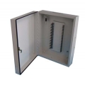
 ฝาใส กว้าง(200) x สูง(150) x ลึก(100) มม.")


")


 (COMS-NET)")

 ฝาใส มีหลังคา กว้าง(300) x สูง(300) x ลึก(130) มม.")
/01 VINYL-INSULATED RING TERMINALS-120x120.jpg "หางปลากลม แบบหุ้มไวนีล (V-Series) (1.5 - 2.5 sq.mm.) RVL2-3.7")

/03 Building Cable/01 Building and Audio/27/VTF CABLE-120x120.jpg "VTF CABLE 1 Pair x 1.50 Sq.mm")

/05 Special Cable/03 Self Support Crane Control Cable/Self Support Crane Control Cable 02-120x120.jpg "Self Support Crane Control Cable PVC Insulated, PVC Jacket 600V-Double Sling 1.50 sq.mm. 8 Cores")


/01 NON-INSULATED DIN 46228 CORD END TERMINALS-120x120.jpg "ข้อต่อย้ำปลายสายเดี่ยว แบบเปลือย DIN 46228 (4.0 คร.มม.) EN4010")
")


/22 NON-INSULATED PIN TERMINALS-38x38.jpg)

 ไปรษณีย์ไทย
 สินค้าน่าสนใจ


-38x38.jpg)


-38x38.jpg)
 DBD Registered
1.25Gbps CWDM SFP Transceiver, 80KM
 กดเพื่อขยายขนาด |
|
1.25Gbps CWDM SFP Transceiver, 80KM
Features :-
- SFP package with LC connector
- CWDM DFB laser with Isolator and PIN photo detector
- Up to 80Km transmission on SMF
- +3.3V single power supply
- LVPECL compatible data input/output interface
- Low EMI and excellent ESD protection
- Laser safety standard IEC-60825 compliant
- Digital Diagnostic SFF-8472 compliant
Description :-
SFP (small form-factor pluggable) or mini-GBIC input/output transceivers are compact and hot-pluggable for converting optical and electrical media; it is widely used for both data communication and telecommunication applications. Moreover, this SFP are fully compliant with the SFP MSA (Multisource Agreement) specifications, and specially designed to support SONET, Ethernet, Fiber Channel, and other communications standards.
This CWDM SFP transceiver supports dual data-rate of 1.25Gbps and transmission distance of 80km with SMF (Single-mode Fiber). The SFP Transceivers consist of three sections: an un-cooled CWDM DFB laser transmitter, a PIN photodiode integrated with a trans-impedance preamplifier (TIA) and MCU control unit. All modules satisfy class I laser safety requirements. Furthermore, the transceivers are compatible with SFP Multi-Source Agreement (MSA) and SFF-8472. For further information, please refer to SFP MSA.
Specification : -
Absolute Maximum Rating:
| Parameters |
Symbol |
Min. |
Max. |
|
Storage Temperature (°C) |
Tst |
-40 |
+85 |
|
Operating Humidity |
Ts |
5 |
95 |
|
Supply Voltage (V) |
Vcc |
-0.5 |
+3.6 |
Operation Environment:
| Parameters |
Symbol |
Min. |
Typ. |
Max. |
|
Standard Operation Case Temp. (°C) |
Tc |
0 |
|
+70 |
|
Supply Voltage (V) |
Vcc |
3.13 |
3.3 |
3.47 |
|
Power Supply Current (mA) |
Top |
|
|
300 |
|
Data Rate (Gb/s) |
- |
- |
1.25 |
- |
lC Wavelength Guide:
| λC Wavelength Guide | |||||||||||
|
Code |
λC |
Unit |
Code |
λC |
Unit |
Code |
λC |
Unit |
Code |
λC |
Unit |
|
27 |
1270 |
nm |
37 |
1370 |
nm |
47 |
1470 |
nm |
57 |
1570 |
nm |
|
29 |
1290 |
nm |
39 |
1390 |
nm |
49 |
1490 |
nm |
59 |
1590 |
nm |
|
31 |
1310 |
nm |
41 |
1410 |
nm |
51 |
1510 |
nm |
61 |
1610 |
nm |
|
33 |
1330 |
nm |
43 |
1430 |
nm |
53 |
1530 |
nm |
|
|
|
|
35 |
1350 |
nm |
45 |
1450 |
nm |
55 |
1550 |
nm |
|
|
|
Optical and Electrical Characteristics:
![]()
Notes:
1. The optical power is launched into SMF.
2. PECL input, internally AC-coupled and terminated.
3. Measured with a PRBS 27-1 test pattern @1250Mbps, BER ≤1×10-12.
4. Internally AC-coupled.
Timing and Electrical:
![]()
Diagnostics Specifications:
![]()
Digital Diagnostic Memory Map:
The transceivers provide serial ID memory contents and diagnostic information about the present operating conditions by the 2-wire serial interface (SCL, SDA).
The diagnostic information with internal calibration or external calibration all are implemented, including received power monitoring, transmitted power monitoring, bias current monitoring, supply voltage monitoring and temperature monitoring.
The digital diagnostic memory map specific data field defines as following.
![]()
PIN Diagram:
![]()
Pin Description:
![]()
Notes: Plug Seq.: Pin engagement sequence during hot plugging.
1. TX Fault is an open collector output, which should be pulled up with a 4.7k~10kΩ resistor on the host board to a voltage between 2.0V and Vcc+0.3V. Logic 0 indicates normal operation; Logic 1 indicates a laser fault of some kind. In the low state, the output will be pulled to less than 0.8V.
2. TX Disable is an input that is used to shut down the transmitter optical output. It is pulled up within the module with a 4.7k~10kΩ resistor. Its states are:
Low (0 to 0.8V): Transmitter on
(>0.8V, < 2.0V): Undefined
High (2.0 to 3.465V): Transmitter Disabled
Open: Transmitter Disabled
3. Mod-Def 0,1,2. These are the module definition pins. They should be pulled up with a 4.7k~10kΩ resistor on the host board. The pull-up voltage shall be VccT or VccR.
Mod-Def 0 is grounded by the module to indicate that the module is present
Mod-Def 1 is the clock line of two wire serial interface for serial ID
Mod-Def 2 is the data line of two wire serial interface for serial ID
4. LOS is an open collector output, which should be pulled up with a 4.7k~10kΩ resistor. Pull up voltage between 2.0V and Vcc+0.3V. Logic 1 indicates loss of signal; Logic 0 indicates normal operation. In the low state, the output will be pulled to less than 0.8V.
5. RD-/+: These are the differential receiver outputs. They are internally AC-coupled 100 differential lines which should be terminated with 100Ω (differential) at the user SERDES.
6. TD-/+: These are the differential transmitter inputs. They are internally AC-coupled, differential lines with 100Ω differential termination inside the module.
Application :-
- Ethernet
- Telecom
- Fiber Channel
![]()
Recommended Application Circuit:
![]()
ความคิดเห็น: คำแนะนำ: HTML จะไม่ถูกแปลง!
ความนิยม: แย่ ดี
ป้อนรหัสในกล่องข้างล่างนี้: